Category Archives: Hardware Hacking

avr11: how to add 256 kilobytes of ram to an Arduino

18 bits of core memory

In Schmidt’s original javascript simulator, and my port to Go, the 128 kilowords (256 kilobytes) of memory connected to the PDP-11 is modeled using an array. This is a very common technique as most simulators execute on machines that have many more resources than the machines they impersonate.

However, when I started to port my Go based simulator to the Arduino, the problem I faced was the Atmel does not support an address space larger than 64 kilobytes, and more immediate, all the 8 bit Atmega models ship with somewhere between 2kb and 8kb of addressable memory.

Version 0, use the Arduino itself

Deciding to put that problem to the side until I saw if the job of rewriting (and dusting off my long obsolete C coding skills) was achievable, the first version of the simulator I wrote did use a simple array for UNIBUS memory.

#define MEMSIZE 2048
uint16_t memory[MEMSIZE];

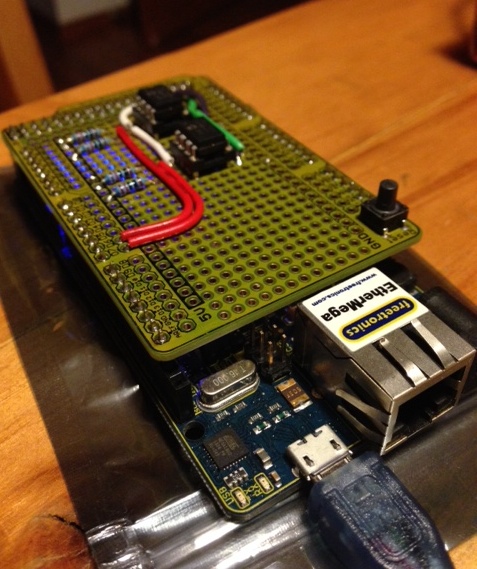
Using an Atmega2560 I was able to create a memory of 4096 bytes, which was enough to bring up the simulator and run the short 29 word bootstrap program which loaded the V6 Unix bootloader into memory.

Sadly the bootloader would fault the simulated CPU almost immediately as the first thing the bootloader does is zero the entire address space, quickly running past the end of the array and overwriting something important.1

However, this did let me get to the point that the CPU and RK11 drive simulators were working well, not to mention figuring out how to write a large multi file program using the Arduino IDE environment.

Memory lives somewhere else

A revelation I have recently arrived at is that, from the point of view of a CPU, memory is not part of the processor. Data in a real CPU moves into and out of the device in a very orchestrated manner and in avr11 this is no different.

Any instruction that references memory, either directly loading data into a register via the MOV instruction, or indirectly using one of the PDP-11’s addressing modes always boiled down to a read or write function which linked the CPU to the simulated UNIBUS.

For example, in the Go version of the simulator, memory []uint16 belongs to the unibus struct. In the C++ version for Atmel this is enforced further by there being no extern uint16_t memory[MEMSIZE]; definition exposed in unibus.h.

In short, there is no way for the CPU to observe memory, it has to ask the UNIBUS to read or write data on its behalf, and this gave me the opportunity to solve the problem of limited memory space available on the Atmel devices I had access to.

Version 1, I am a bad person

At this point I’m sort of telling the story backwards. I had found a product which would give me far more memory than I needed for this project, but it took several weeks to arrive and comes as a kit, which will involve some tricky SMD soldering.

In the interim I found myself during the Christmas to New Years break with a simulator that I felt was working well enough to try something more adventurous if I could only find some way to emulate the backing array for the core memory. I didn’t really care about speed, I just wanted to see if the simulator could handle the more complicated instructions of the Unix kernel.

“Why not use the SD card?” I said to myself. I was after all already loading some of the blocks off the RK05 disk pack image from the card, so why not just make another image file and make that back the core memory. The mini SD card probably wouldn’t last very long, but I have a pile of cheap cards so why not try it.

 void pdp11::unibus::write8(uint32_t a, uint16_t v) {
    if (a < 0760000) {
       if (a & 1) {
         core.seek(a);
         core.write(v & 0xff);
         //memory[a >> 1] &= 0xFF;
         //memory[a >> 1] |= v & 0xFF << 8;

All it took was setting up a new SD::File, called core and rewriting the access to the memory array with seeks and writes to the backing file (obviously doing the same for the read paths).

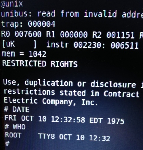
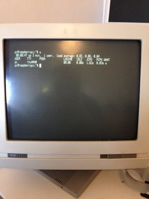
Amazingly it worked, on the second or third attempt, and although it was very slow I was able to use this technique to boot the simulator a very long way into the Unix boot process. I posted a video of the bootup to instagram.

Even more amazingly I didn’t wear out the mini SD card, and still haven’t. This is probably mostly due to the wear leveling built into the card2 but I also stumbled into a fortuitous property of the SD card itself, and the Arduino drivers on top.

All SD cards, well certainly SD and mini SD cards, mandate that you read and write to them in units of pages. Pages happen to be 512 bytes, a unit which clearly descends from the days of CF cards which emulated IDE drives.

This means the Arduino SD class maintains a buffer of 512 bytes, (which comes out of your precious SRAM allotment) that in effect operated as a cache for my horrible all swap based memory system. For example, when the bootloader program zeros all the memory in the machine, rather than writing to the SD card 253,952 times3, the number of writes was probably much smaller, say 500 writes.

Obviously as it was not designed for this purpose the cache would fail badly during a later part of the bootup where the kernel code is copied (about 90 kilowords of it) from one memory area to another. Each read or write would land on a different SD card page, causing it to flush the old buffer, read in the new buffer, then reverse the process.

But it worked, and gave me confidence to investigate some more ambitious designs for a memory solution.

In my next blog post I’ll talk about version 2 of my memory system, the one that I finally got me booting to the # prompt.


  1. I considered using a SAM3X atmel32 style board, like the Arduino Due as they have both a more powerful CPU and close to 96 kilobytes of addressable memory, but that is only 48 kilowords, less than half of what I need to simulate the full 128 kiloword address space of the PDP-11.
  2. The internet is divided on the question of “Do cheap mini SD cards have wear leveling?”. Part of the problem is the definition of cheap changes rapidly over time, making advice written 12 months ago inaccurate. My view is that cards of any capacity you can buy today require so much error correction logic that you get the wear leveling logic for free.
  3. On the PDP the top 4 kilo words of memory (8kb) is reserved for the IO devices, so while the UNIBUS talks in 18 bit addresses, the top 4096 words is not mapped to memory, and doesn’t need to be cleared. In fact clearing the IO page memory would be catastrophic.

avr11: simulating minicomputers on microcontrollers

Introduction

The avr11, a atmega2560 clone with a custom SPI 256kb memory.

The avr11, an atmega2560 clone with a custom SPI 256kb memory.

It all started with Javascript.

In April of 2011 Julius Schmidt wrote a PDP-11 emulator that ran in a browser. I thought that this was one of the most amazing thing I had ever seen.

Late last year I ran across the link again in my Pocket backlog and spent a little time poking around the code that powered the simulator.

The PDP-11 architecture is very interesting. All the the major system components work asynchronously, co-ordinating access via the shared UNIBUS backplane. Julius’ simulator used this property and callbacks on timers to simulate components like the disk and console operating asynchronously.

I’ve written previously about the suitability of Go for writing emulators and so I thought it would be a fun project to port Julius’ work to Go. This port is going well and provided the base for porting the code to C++ for this project.

Around the same time I ran across several other projects which convinced me to try an Atmel port.

The first was the winner of last years IOCCC, a 4k Intel 8086 simulator1 which showed me that the core of a CPU simulator could be small. Ignoring main memory, you need only simulate the small number of registers defined by the architecture. The PDP-11 has 8 16bit registers, a few service registers and 32 16 bit mmu registers2 to hold mappings. This would fit even in a small microcontroller like the 328p or 32u4.

The second project was a hardware implementation of a 32bit ARM CPU running linux on an Atmel 128p. Probably built as a dare, this project showed me that reliable simulators can be built on the 8bit Atmel platform and an external device could be used to represent the larger main memory expected by the CPU being simulated.

Maybe this wasn’t as crazy as it sounded.

Why the PDP-11 ?

PDP11/45 console. Image courtesy of John Holden's PDP11 page.

PDP-11/45 console. Image courtesy of John Holden’s PDP-11 page.

The PDP-11 is the most important minicomputer of the 1970’s.

The cost of the PDP-11 was low enough that it could be dedicated to one person or small group when mainframe computers cost so much to run that time was billed by the hour to recoup their phenomenal cost. DEC machines quickly became the platform for research and experimentation.

The PDP-11 was the machine that Ken Thompson and Dennis Ritchie developed Unix and the C programming language. As a historical artefact it has tremendous importance for anyone who is interested in computer programming or retro computing.

If you want to know why the int datatype in C defaults to 16 bits, look at the PDP-11, it was a 16 bit computer. If you want to know why a char is called a char not a byte look to way the PDP-11 stored two characters in a word.

So, what better way to learn about the PDP-11, and the history of C and Unix, than to build a simulator of the machine that started it all ?

Why build a simulator on a microcontroller?

Let’s be honest, the world doesn’t need another Arduino weather station.

Apart from wiring up LED and LCD displays I haven’t really found anything that really excites me about using microcontrollers. In some ways, the way that microcontrollers are coded and used feels very batch oriented — write some code, compile it, load it onto the micro, wait quietly to see it it worked, rinse, repeat.

I had heard a Podcast interview with one of the makers of the Pebble smart watch and learnt about the Pebble OS, a fork of FreeRTOS.

FreeRTOS looked like as a way to write interactive programs on microcontrollers, and those ideas were percolating inside my head while I was porting Julius’ Javascript simulator to Go over Christmas.

One of the nice features of Julius’ simulator was the very clean separation between the CPU logic and the memory logic. In the PDP-11 memory is just another device on the UNIBUS bus and so I began to think that if I could find some way of connecting the required 128 kilowords of memory to an Atmel the rest of the simulator should fit within the onboard SRAM.

What works today

A screenshot of one of the first successful boot attempts.

A screenshot of one of the first successful boot attempts.

Today the simulator boots V6 unix and can execute some simple commands, there are some remaining bugs in the mmu which cause the simulator to fail when larger programs (/usr/bin/cc and /usr/games/chess for example) are executed

The hardware emulated is somewhere between a PDP11/40 and PDP11/45. The EIS option (MUL and DIV) is properly emulated, but FIS (floating point is not).

Only a single RK05 drive is simulated, backed by a file on the micro SD card.

I want to improve the accuracy of the simulator so that it can run V7 unix, 2.9/2.11 BSD, RSX-11M and most importantly, the DEC diagnostics.

All these improvements are first developed on the Go port then will be integrated into the Atmel port.

How is the performance?

Right now, not great. I don’t have a real PDP-11 for comparison, but looking at some videos on Youtube I’d have to say the simulator is at least 10x slower than an original 11/40.

I was never expecting to be amazed with the speed of this simulator, especially at this early stage. However, on a performance per watt basis, I think it’s hard to beat avr11.

The PDP-11 that this simulator models is spartan, even by the standards of the early 70s, yet still consumed over 2 kilowatts of power for the CPU and Memory (256kb). The 2.5 megabyte RK05 boot drive was another 600 watts. Real unix installations would have 3 or more drives, so there goes another 1200-1800 watts.

Compared to that, the avr11 draws well under the 500ma limit of a USB port. Although I lack equipment to measure the current draw I estimate it to be around 100ma at 5 volts which is 0.5 watts. Tell that to your data center manager.

Some specific performance issues I am aware of are:

  1. 32 bit register operands. Everything in the CPU is treated as a 32 bit integer during the simulation of the individual instructions. This is a hold over from the original Javascript simulation. The Atmel is internally an 8 bit CPU. There are provisions for 16 bit, double byte operations, but they come at a cost of 5x over their 8 bit counterparts. Using 32 bit operands are even more costly again.
  2. SPI memory. The overhead of the SPI transaction to read a word from memory is quite high. As most instructions generate at least 2 memory cycles, and can be as high as 6, fetching operands from memory consumes a lot of wall time.

Getting the code

Julius’ original Javascript implementation, from which both my Go and Atmel ports derive, is licensed under the liberal WTFPL licence. As I share similar views on software licensing, both of my projects will be similarly licensed.

The code itself is on Github. As of today it is frankly a dog’s breakfast of babies first C++ programming and Arduino hacks. As the project progresses I hope this will improve.

Ethermega and SPI SRAM shield.

Ethermega and SPI SRAM shield (unpopulated).

However the code itself isn’t much use without the hardware. Again this is under heavy flux and I hope to improve the number platforms the simulator can run on.

The specific hardware requirements are an Atmega2560 (the older 1280 will also work, I just don’t have one to experiment with). I’m using the Freetronics Ethermega, mainly because it was what I could buy at Jaycar, but also because it has a built in micro SD card reader onboard.

The SPI SRAM shield is custom, and I’ll be writing about it in my next post.


  1. The author of 8086tiny has recently released a de-obfuscated version of their emulator.
  2. Actually Julius’ emulator cheated, there are actually 3 banks of 16 mmu registers in a real KT11 mmu, but V6 unix doesn’t use supervisor mode, so we can cheat a little here.

A real serial console for your Raspberry Pi

rpi-consoleThis post talks about how I connected my Raspberry Pi to a WYSE 60 terminal.

Voltages

The terminal speaks RS232 level, +/- 12v, but the Pi speaks 3.3v TTL levels so some sort of converter is needed to adapt the signalling levels. A logic level converter won’t work as RS232 signalling needs negative voltages as well.

photo (4)

Fortunately Sparkfun sell a great little kit called the RS232 Shifter Board Kit which converts TTL to RS232 levels.

The picture on the left is the SMD version which comes pre made, I also bought the kit version which I am using to connect the RPi. I believe they are identical in function.

Connectors

photo 1The next issue is connecting the terminal to the level shifter. Luckily because the WYSE terminal is hard wired to be a DTE, the RPi falls naturally into its role as a DCE. What does this mean ? It means I didn’t need to build a null modem cable, a short cable to extend the DB9 connector around to the back of the terminal (where I have a DB-9 to DB-25 adapter) was all that was necessary.

A quick trip to Jaycar and I had a few feet of ribbon cable and some DB-9 ribbon cable connectors. Just match up pin 1 on both ends then hammer the plastic bracket to crimp the ribbon cable into the housing.

Wiring

photo 3The image on the left shows how I wired up the RS232 converter to my Pi.

The Pi is connected via a ribbon cable on the P1 header to a breakout connector which lets me plug it into a breadboard.

photo 3In the image on the right you can see the breakout board which lets me tap into the various pins on the P1 header easily.

I’m also providing power to the Pi over the P1 header via the breadboard and my Dangerous Prototypes ATX breakout board.

Between the RS232 converter and the Pi is a level shifter which is translating 3.3v TTL levels from the TX and RX pins to 5v. In theory this shouldn’t be necessary as the RS232 converter is supposed to be able to handle voltages as low as 2.8v but is really designed for interfacing with Arduinos, so shifting the RX and TX signals up to 5v couldn’t hurt.

Setting up the Pi

On last issue to overcome was the Pi by default runs the console at 115,200 baud while the WYSE terminal maxes out at 19,200. To set the operating baud for the console device to be 19,200 baud, you need to edit these two files

  • /boot/cmdline.txt, update the two references to 115200 to 19200.
    dwc_otg.lpm_enable=0 console=ttyAMA0,19200 kgdboc=ttyAMA0,19200 console=tty1 root=/dev/mmcblk0p2 rootfstype=ext4 elevator=deadline rootwait
  • /etc/inittab, updating the line at the bottom, referencing ttyAMA0 to also be 19200.
    #Spawn a getty on Raspberry Pi serial line
    T0:23:respawn:/sbin/getty -L ttyAMA0 19200 vt100

And that is it. Hook everything up and reboot.

Console in action

photo 2I posted a short video of the RPi booting up on instragram.

So, why would you want to do this when PL2303 serial to USB adapters are cheap and available? Well, there is no good reason, apart from it was there, and I had the parts.

Installing Ubuntu Precise 12.04 on a Udoo Quad

Udoo Quad

This is a quick post explaining how to install Ubuntu 12.04 on your Udoo Quad board (I’m sure the instructions can be easily adapted to the Dual unit as well).

The Udoo folks have made available two distributions, Linaro Ubuntu 11.10 and Android 4.22. The supplied Linaro distribution is very good, running what looks like Gnome 3 and comes with Chrome and Arduino IDE installed to get you started. If you want to just enjoy your Udoo then you could do a lot worse than sticking with the default distro.

Ubuntu Core

Canonical makes a very small version of Ubuntu called Ubuntu Core. Core is, as its name suggests, the bare minimum required to boot the OS.

As luck would have it there is a version for 12.04 for armhf so I thought I would see if I could get Ubuntu Core 12.04 running on the Udoo. There weren’t a lot of docs on the boot sequence for the Udoo, but I had enough experience with other Uboot based systems to figure out that Uboot is written directly to the start of the card, which then mounts your root partition and looks for the kernel there.

The first step is to download and dd the Udoo supplied image to a micro sd card and boot it up. I then did the same to a second micro sd card and connected that to the Udoo with a USB card reader.

There are probably ways to avoid having to use two cards, but as Ubuntu Core is so minimal it helps to have a running arm system that you can chroot to the Ubuntu 12.04 image and apt-get some more packages that will make it easier to work with (ie, there is no editor installed in the base Ubuntu Core image).

Once the Udoo is booted up using the Linaro 11.10 image, perform the following steps as root.

Erase the root partition on the target sdcard and mount it.

# mkfs.ext3 -L udoo_linux /dev/sda1
# mount /dev/sda1 /mnt

Unpack the Ubuntu Core distro onto the target

# curl http://cdimage.ubuntu.com/ubuntu-core/releases/12.04/release/ubuntu-core-12.04.3-core-armhf.tar.gz | tar -xz -C /mnt

Next you need to copy the kernel and modules from the Linaro 11.10 image

# cp -rp /boot/uImage /mnt/boot/
# cp -rp /lib/modules/* /mnt/lib/modules/

At this point the new Ubuntu 12.04 image is ready to go, but it is a very spartan environment so I recommend the following steps

# chroot /mnt
# adduser $SOMEUSER
# adduser $SOMEUSER adm
# adduser $SOMEUSER sudo
# apt-get update
# apt-get install sudo vim-tiny net-tools # and any other packages you want

Fixing the console

The Udoo serial port operates at 115200 baud, but by default the Ubuntu Core image is not configured to take over on /dev/console at the correct baud. The simplest solution to fix this is

# cp /etc/init/tty1.conf /etc/init/console.conf

Edit /etc/init/console and change the last line to

exec /sbin/getty -8 115200 console

And that is it, exit your chroot

# exit

Unmount your 12.04 partition

# umount /mnt
# sync

Shutdown your Udoo, take out the Linaro 11.10 image, insert your 12.04 image and hit the power button. If everything worked you should see a login prompt on the screen, if you have connected a HDMI monitor, and the serial port if you’ve connected the port up (recommended).

After that, login as the user you added above, sudo to root and finish your setup of the host.

Udoo quad hooked up and runningOh, and in case you were wondering, early Go benchmarks put this board about 20% faster than my old Pandaboard Dual A9 and 10% faster than my recently acquired Cubieboard A7 powered hardware.

One feature I really appreciate is the onboard serial (UART) to USB adapter which means you can get access to the serial console on the Udoo with nothing more than a USB A to Micro B cable.

Two point five ways to access the serial console on your Beaglebone Black

Introduction

I recently purchased a Beaglebone Black (BBB) as a replacement for a Raspberry Pi which was providing the freebsd/arm builder for the Go build dashboard. Sadly the old RPi didn’t work out. I’m hoping the BBB will be a better match, faster, and more reliable.

The BBB is a substantial upgrade to the original Beaglebone for a couple of reasons.

The first is obviously the price. At less than $50 bucks AUD in my hand, it offers substantially better value for money than the original BB. This drive towards a lower price point is clearly a reaction to Arduinos and the Raspberry Pi. Having now owned both I can see the value the original BB offered, it’s a much better integrated package, but newcomers to embedded systems will vote with their wallets.

Secondly, the new BBB comes with 512mb of RAM onboard, up from the 256mb of its predecessor. For a freebsd/arm builder, this is very important. You also get 2gb of eMMc flash onboard, which comes preinstalled with Angstrom Linux.

Lastly, the processor has been bumped from 720Mhz to 1Ghz, providing you can provide sufficient current.

Of the original Beaglebone features that were cut were JTAG and serial over USB. This last point, the lack of a serial port, is the focus of the remainder of this article.

The serial pins on your Beaglebone Black

J1 serial port header

J1 serial port header

The Beaglebone Black serial port is available via the J1 header. This picture is upside down with respect to the pin numbers, pin 1 is on the right and pin 6 is on the left.

Method number one, the FTDI USB to Serial adapter.

The first, simplest, and most recommended method of connecting to your BBB is via an FTDI USB to Serial adapter. These come in all shapes and sizes, some built into the USB A plug, others like this one are just the bare board. If you’ve done any Arduino programming you’ve probably got a slew of these little things in your kit. I got mine from Little Bird Electronics for $16 bucks.

DFRobot FTDI USB to Serial adapter

DFRobot FTDI USB to Serial adapter

The FTDI adapter can do more than just level convert between USB and the BBB’s 3.3 volt signals. This one can provide power from the USB host at either 3.3 or 5 volt as well as provides breakouts for the other RS232 signals.

Normally avoiding the power supply built into the FTDI adapter would be a problem, but the designers of the BBB have already thought of this and made it super simple to directly connect the FTDI adapter, or cable, to the BBB.

FTDI adapter mounted on the J1 header

Simply put, although the male header on the BBB matches the FTDI adapter, only pins 1, 4 and 5 are actually connected on the board. This means you don’t have to worry about Vcc on pin 3 of the FTDI adapter as the pin on the BBB is not connected.

Method number two, Prolific PL2303 USB to Serial adapter

PL2303 showing the +5v lead

This is the no no wire

The second method is similar to the previous, but this time using a Prolific Technologies PL2303 USB to Serial cable. This cable is very common if you’ve used the Raspberry Pi. I got my first one from Adafruit, but I’ve since received a few more as part of other dev board kits. You can even make your own by cutting the ends of old Nokia DKU-5 cables. Irrespective all the cables use the Prolific Technology PL2303 chipset.

The drawback of the PL2303 is the red wire, this carries +5v from the USB port and can blow the arse out of your BBB. Strictly speaking it can blow up you RPi with this cable if you aren’t careful, but in the case of the BBB, there is no safe pin to connect it; you must leave it unconnected.

PL2303 showing the +5v lead unconnected

To hook up your BBB using the PL2303 connect the black, ground lead to pin 1 on the J1 header, the green RX lead to pin 4, and the white TX lead to pin 5.

Do not connect the red lead to anything!

Method three, using a Bus Pirate as serial passthrough

Bus Pirate in UART passthrough mode

Bus Pirate in UART pass through mode

This last method isn’t really practical as most people are unlikely to have a Bus Pirate, or if they do, they’ll probably also have an FTDI or PL2303 cable knocking about.

Connect the Bus Pirate as described on this page for UART mode, connect to the BP over your serial connectoin, then type this set of commands

m # to set the mode
3 # for UART mode
9 # for 115,200 bps
1 # for 8 bits, no parity
1 # for 1 stop bit
1 # for idle 1 receive polarity
2 # for normal, 3.3v output
(1) # for Transparent bridge mode
y # to start the bridge mode

Connecting to the serial console

Independent of which method to wire up your serial console, you’ll need to connect to it with some terminal software. I recommend using screen(1) for this, although some people prefer minicom(1). If you’re on Windows I think your options are limited to Teraterm Pro, but that is about all I know.

Using screen is as simple as

% sudo screen $USBDEVICE 115200

Which will start a new screen session at the almost universal speed of 115200 baud. The name of your USB device depends on your operating system. To quit screen, hit control-a then k.

Drivers

If you are using Linux, every modern distribution has drivers for the PL2302 and FTDI, nothing is required, but check dmesg(1) for the name of your device.

If you are using OS X, you will neither device is supported out of the box so you will have to download and install the drivers.

Devices names

  • On Linux, the device will be /dev/ttyUSB0 reguardless of the type of cable you are using.
  • On OS X, the name of the device depends on its driver.
    • For the FTDI driver, the device will start with /dev/tty.usbserial, eg, tty.usbserial-AD01U7TH.
    • For the PL2303 driver, the device will start with /dev/tty.PL2303, eg. tty.PL2303-000012FD.

Wrapping it up

I’m really impressed with the Beaglebone Black. While not as powerful as something like a Odroid-X2, or Pandaboard, the integration and out of the box experience is very compelling. Little touches like the layout of the J1 serial header give me confidence that the designers didn’t just aim for the lowest price point throwing quality to the wind; Cubieboard, I’m looking at you.

Should I actually get freebsd/arm up and building on the BBB, I’ll make a separate post about that.

Go 1.1 on the Cubieboard 2

Thanks to Little Bird Electronics I just picked up the recently released Cubieboard 2.
Cubieboard 2
For less than 90 bucks Australian you get the case, 4Gb of onboard NAND flash, a USB to serial adapter, USB to power adapter (althought you should use a real wall wart), and an adapter for the onboard SATA port which can driver the 5 volt rail of a 2.5″ drive directly from the board! This blows the old iMX.53 loco into the weeds.

cubie@Cubian:~/go/test/bench/go1$ go version
go version go1.1.1 linux/arm
cubie@Cubian:~/go/test/bench/go1$ go test -bench=.
testing: warning: no tests to run
PASS
BenchmarkBinaryTree17          1        48584450065 ns/op
BenchmarkFannkuch11            1        39106118893 ns/op
BenchmarkFmtFprintfEmpty         2000000               946 ns/op
BenchmarkFmtFprintfString        1000000              2901 ns/op
BenchmarkFmtFprintfInt   1000000              2111 ns/op
BenchmarkFmtFprintfIntInt         500000              3291 ns/op
BenchmarkFmtFprintfPrefixedInt    500000              3530 ns/op
BenchmarkFmtFprintfFloat          200000              7820 ns/op
BenchmarkFmtManyArgs      100000             13727 ns/op
BenchmarkGobDecode            10         132398137 ns/op           5.80 MB/s
BenchmarkGobEncode            50          62968325 ns/op          12.19 MB/s
BenchmarkGzip          1        5177324419 ns/op           3.75 MB/s
BenchmarkGunzip        5         900631458 ns/op          21.55 MB/s
BenchmarkHTTPClientServer           2000            793348 ns/op
BenchmarkJSONEncode            5         632428975 ns/op           3.07 MB/s
BenchmarkJSONDecode            1        1431043626 ns/op           1.36 MB/s
BenchmarkMandelbrot200        50          43100116 ns/op
BenchmarkGoParse              50          53644104 ns/op           1.08 MB/s
BenchmarkRegexpMatchEasy0_32     1000000              1186 ns/op  26.96 MB/s
BenchmarkRegexpMatchEasy0_1K      500000              4956 ns/op 206.61 MB/s
BenchmarkRegexpMatchEasy1_32     1000000              1205 ns/op  26.55 MB/s
BenchmarkRegexpMatchEasy1_1K      200000             11982 ns/op  85.46 MB/s
BenchmarkRegexpMatchMedium_32    1000000              2066 ns/op   0.48 MB/s
BenchmarkRegexpMatchMedium_1K       5000            680173 ns/op   1.51 MB/s
BenchmarkRegexpMatchHard_32        50000             36728 ns/op   0.87 MB/s
BenchmarkRegexpMatchHard_1K         2000           1115221 ns/op   0.92 MB/s
BenchmarkRevcomp              20         103053970 ns/op          24.66 MB/s
BenchmarkTemplate              1        1372074834 ns/op           1.41 MB/s
BenchmarkTimeParse        200000             11836 ns/op
BenchmarkTimeFormat       200000             10199 ns/op
ok      _/home/cubie/go/test/bench/go1  168.097s

If you compare that to my OMAP4 based pandaboard, Go 1.1 performance is 5 to 10 % better. Not bad.