 This post talks about how I connected my Raspberry Pi to a WYSE 60 terminal.
Voltages
The terminal speaks RS232 level, +/- 12v, but the Pi speaks 3.3v TTL levels so some sort of converter is needed to adapt the signalling levels. A logic level converter won’t work as RS232 signalling needs negative voltages as well.
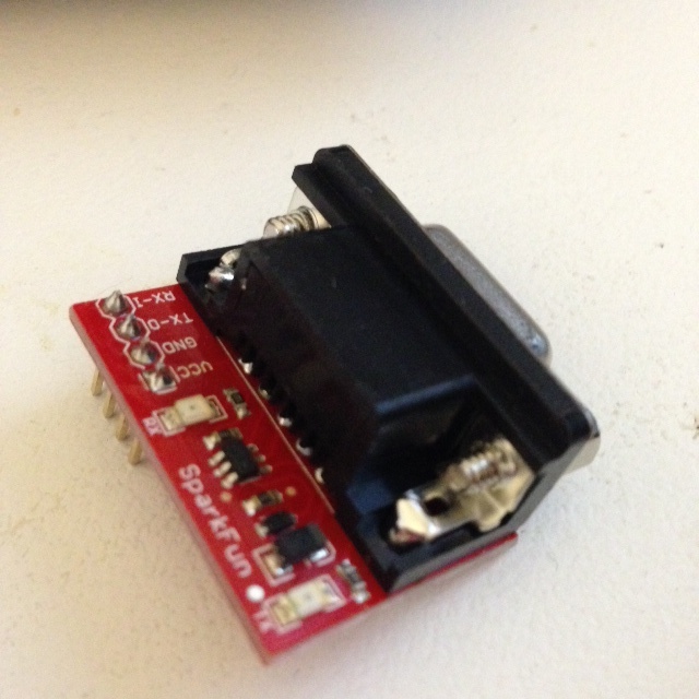
Fortunately Sparkfun sell a great little kit called the RS232 Shifter Board Kit which converts TTL to RS232 levels.
The picture on the left is the SMD version which comes pre made, I also bought the kit version which I am using to connect the RPi. I believe they are identical in function.
Connectors
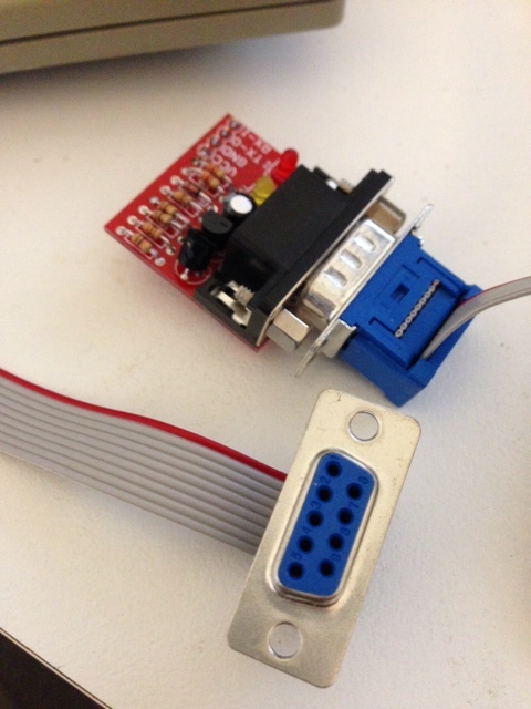 The next issue is connecting the terminal to the level shifter. Luckily because the WYSE terminal is hard wired to be a DTE, the RPi falls naturally into its role as a DCE. What does this mean ? It means I didn’t need to build a null modem cable, a short cable to extend the DB9 connector around to the back of the terminal (where I have a DB-9 to DB-25 adapter) was all that was necessary.
A quick trip to Jaycar and I had a few feet of ribbon cable and some DB-9 ribbon cable connectors. Just match up pin 1 on both ends then hammer the plastic bracket to crimp the ribbon cable into the housing.
Wiring
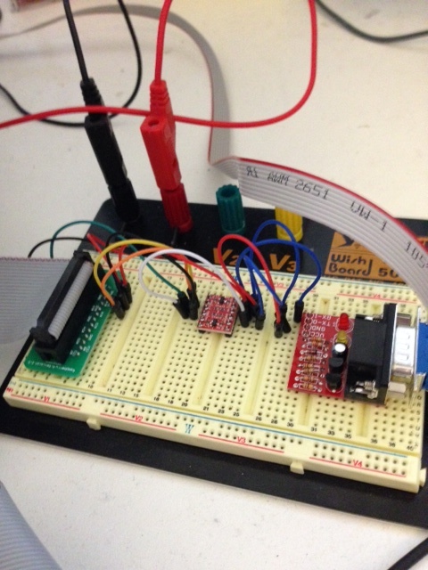
 The image on the left shows how I wired up the RS232 converter to my Pi.
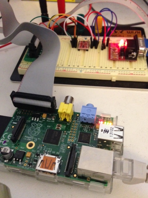
The Pi is connected via a ribbon cable on the P1 header to a breakout connector which lets me plug it into a breadboard.
 In the image on the right you can see the breakout board which lets me tap into the various pins on the P1 header easily.
I’m also providing power to the Pi over the P1 header via the breadboard and my Dangerous Prototypes ATX breakout board.
Between the RS232 converter and the Pi is a level shifter which is translating 3.3v TTL levels from the TX and RX pins to 5v. In theory this shouldn’t be necessary as the RS232 converter is supposed to be able to handle voltages as low as 2.8v but is really designed for interfacing with Arduinos, so shifting the RX and TX signals up to 5v couldn’t hurt.
Setting up the Pi
On last issue to overcome was the Pi by default runs the console at 115,200 baud while the WYSE terminal maxes out at 19,200. To set the operating baud for the console device to be 19,200 baud, you need to edit these two files
- /boot/cmdline.txt, update the two references to 115200 to 19200.
dwc_otg.lpm_enable=0 console=ttyAMA0,19200 kgdboc=ttyAMA0,19200 console=tty1 root=/dev/mmcblk0p2 rootfstype=ext4 elevator=deadline rootwait
- /etc/inittab, updating the line at the bottom, referencing ttyAMA0 to also be 19200.
#Spawn a getty on Raspberry Pi serial line
T0:23:respawn:/sbin/getty -L ttyAMA0 19200 vt100
And that is it. Hook everything up and reboot.
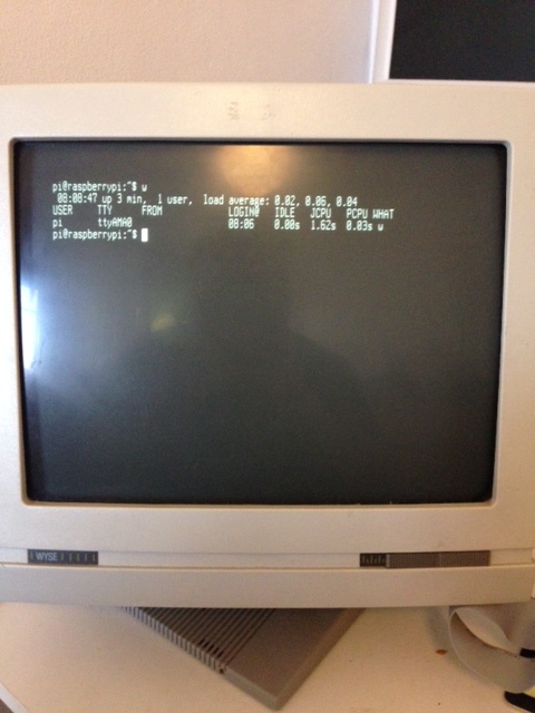
Console in action
 I posted a short video of the RPi booting up on instragram.
So, why would you want to do this when PL2303 serial to USB adapters are cheap and available? Well, there is no good reason, apart from it was there, and I had the parts.