Introduction
I recently purchased a Beaglebone Black (BBB) as a replacement for a Raspberry Pi which was providing the freebsd/arm builder for the Go build dashboard. Sadly the old RPi didn’t work out. I’m hoping the BBB will be a better match, faster, and more reliable.
The BBB is a substantial upgrade to the original Beaglebone for a couple of reasons.
The first is obviously the price. At less than $50 bucks AUD in my hand, it offers substantially better value for money than the original BB. This drive towards a lower price point is clearly a reaction to Arduinos and the Raspberry Pi. Having now owned both I can see the value the original BB offered, it’s a much better integrated package, but newcomers to embedded systems will vote with their wallets.
Secondly, the new BBB comes with 512mb of RAM onboard, up from the 256mb of its predecessor. For a freebsd/arm builder, this is very important. You also get 2gb of eMMc flash onboard, which comes preinstalled with Angstrom Linux.
Lastly, the processor has been bumped from 720Mhz to 1Ghz, providing you can provide sufficient current.
Of the original Beaglebone features that were cut were JTAG and serial over USB. This last point, the lack of a serial port, is the focus of the remainder of this article.
The serial pins on your Beaglebone Black
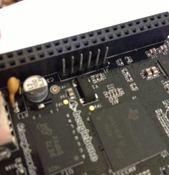
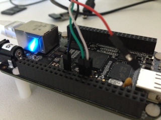
The Beaglebone Black serial port is available via the J1 header. This picture is upside down with respect to the pin numbers, pin 1 is on the right and pin 6 is on the left.
Method number one, the FTDI USB to Serial adapter.
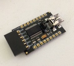
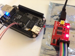
The first, simplest, and most recommended method of connecting to your BBB is via an FTDI USB to Serial adapter. These come in all shapes and sizes, some built into the USB A plug, others like this one are just the bare board. If you’ve done any Arduino programming you’ve probably got a slew of these little things in your kit. I got mine from Little Bird Electronics for $16 bucks.
The FTDI adapter can do more than just level convert between USB and the BBB’s 3.3 volt signals. This one can provide power from the USB host at either 3.3 or 5 volt as well as provides breakouts for the other RS232 signals.
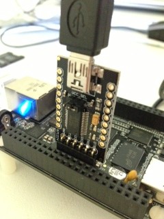
Normally avoiding the power supply built into the FTDI adapter would be a problem, but the designers of the BBB have already thought of this and made it super simple to directly connect the FTDI adapter, or cable, to the BBB.
Simply put, although the male header on the BBB matches the FTDI adapter, only pins 1, 4 and 5 are actually connected on the board. This means you don’t have to worry about Vcc on pin 3 of the FTDI adapter as the pin on the BBB is not connected.
Method number two, Prolific PL2303 USB to Serial adapter
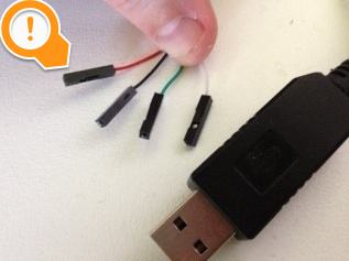
The second method is similar to the previous, but this time using a Prolific Technologies PL2303 USB to Serial cable. This cable is very common if you’ve used the Raspberry Pi. I got my first one from Adafruit, but I’ve since received a few more as part of other dev board kits. You can even make your own by cutting the ends of old Nokia DKU-5 cables. Irrespective all the cables use the Prolific Technology PL2303 chipset.
The drawback of the PL2303 is the red wire, this carries +5v from the USB port and can blow the arse out of your BBB. Strictly speaking it can blow up you RPi with this cable if you aren’t careful, but in the case of the BBB, there is no safe pin to connect it; you must leave it unconnected.
To hook up your BBB using the PL2303 connect the black, ground lead to pin 1 on the J1 header, the green RX lead to pin 4, and the white TX lead to pin 5.
Do not connect the red lead to anything!
Method three, using a Bus Pirate as serial passthrough
This last method isn’t really practical as most people are unlikely to have a Bus Pirate, or if they do, they’ll probably also have an FTDI or PL2303 cable knocking about.
Connect the Bus Pirate as described on this page for UART mode, connect to the BP over your serial connectoin, then type this set of commands
m # to set the mode
3 # for UART mode
9 # for 115,200 bps
1 # for 8 bits, no parity
1 # for 1 stop bit
1 # for idle 1 receive polarity
2 # for normal, 3.3v output
(1) # for Transparent bridge mode
y # to start the bridge mode
Connecting to the serial console
Independent of which method to wire up your serial console, you’ll need to connect to it with some terminal software. I recommend using screen(1) for this, although some people prefer minicom(1). If you’re on Windows I think your options are limited to Teraterm Pro, but that is about all I know.
Using screen is as simple as
% sudo screen $USBDEVICE 115200
Which will start a new screen session at the almost universal speed of 115200 baud. The name of your USB device depends on your operating system. To quit screen, hit control-a then k.
Drivers
If you are using Linux, every modern distribution has drivers for the PL2302 and FTDI, nothing is required, but check dmesg(1) for the name of your device.
If you are using OS X, you will neither device is supported out of the box so you will have to download and install the drivers.
- For the PL2303, I recommend the instructions from the Adafruit website.
- For the FTDI the best source of drives is the Future Technologies website.
Devices names
- On Linux, the device will be
/dev/ttyUSB0reguardless of the type of cable you are using. - On OS X, the name of the device depends on its driver.
- For the FTDI driver, the device will start with
/dev/tty.usbserial, eg,tty.usbserial-AD01U7TH. - For the PL2303 driver, the device will start with
/dev/tty.PL2303, eg. tty.PL2303-000012FD.
- For the FTDI driver, the device will start with
Wrapping it up
I’m really impressed with the Beaglebone Black. While not as powerful as something like a Odroid-X2, or Pandaboard, the integration and out of the box experience is very compelling. Little touches like the layout of the J1 serial header give me confidence that the designers didn’t just aim for the lowest price point throwing quality to the wind; Cubieboard, I’m looking at you.
Should I actually get freebsd/arm up and building on the BBB, I’ll make a separate post about that.

