A few months ago I upgraded the hardware my avr11 project ran on from the atmega2560 8bit micro to the SAM3x based Arduino Due. In doing so I lost access to the excellent QuadRAM memory expansion board, and had to find another solution for accessing the micro SD card.
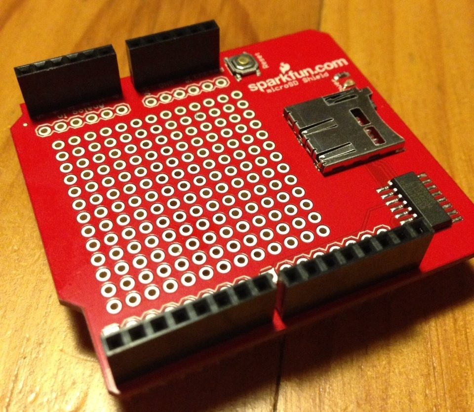
For the moment, I’ve decided to go back to my SPI based SRAM shield that I built previously and this means I need to hook both the SPI SRAM shield and a Sparkfun micro SD card shield up to the Arduino Due.
This brings me to the topic for this post; why do Arduino keep moving the SPI pins!
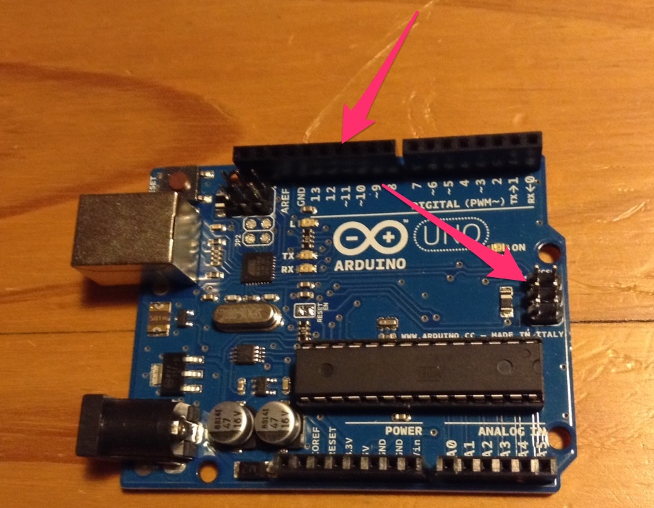
In the beginning there was the Arduino Uno form factor, SPI was available on both pins 11, 12 and 13 as well as the dedicated ICSP header.
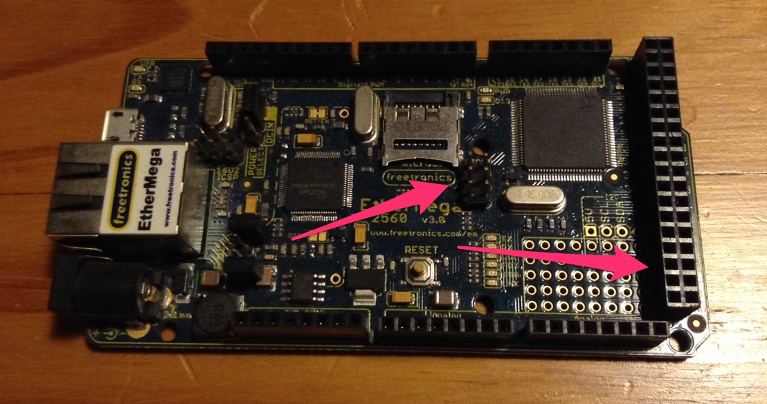
Then the Arduino mega platform came out, with the Atmel 2560 chipset and the larger shield sizes.
SPI is no longer available on pins 11, 12 and 13, but has moved to pins 51, 52 and 32. It remains available on the ICSP header, which is the area that Arduino is pushing shield makers to use. Unfortunately shield makers are steadfastly ignoring the recommendations from Arduino and none of the SD card shields I ca find have a connector to route the ICSP header upwards as you add additional shields. The blanks shields from Freetronics don’t even make it an option.
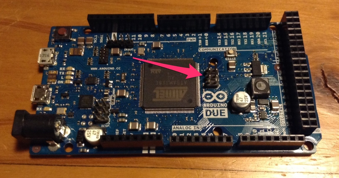
This brings me to the Arduino Due, which I needed to get the grunt to run my avr11 simulator.
To use SPI on the Due I need to somehow route the ISCP connector to pins 11, 12 and 13.
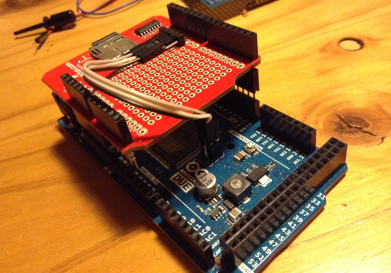
The best solution I had at the time was to raise the shield away from the Due using stacked headers, then route the ISCP signals to the pins that the board (and the SDFat software) expected to find them with some jumper cables. Out of shot, pins 11, 12 and 13 were bent upwards so they did not make contact with the sockets on the Due board.
This was where the project stalled for a few months.
Recently I’ve had some time to come back to this project, and the first order of business was solving the SPI problem. It was clear that pins 11, 12 and 13 were the rightful place for the SPI signals and to try to route them anywhere else would be fruitless. So, with an official Arduino expansion shield in hand, I made myself an SPI adapter board.
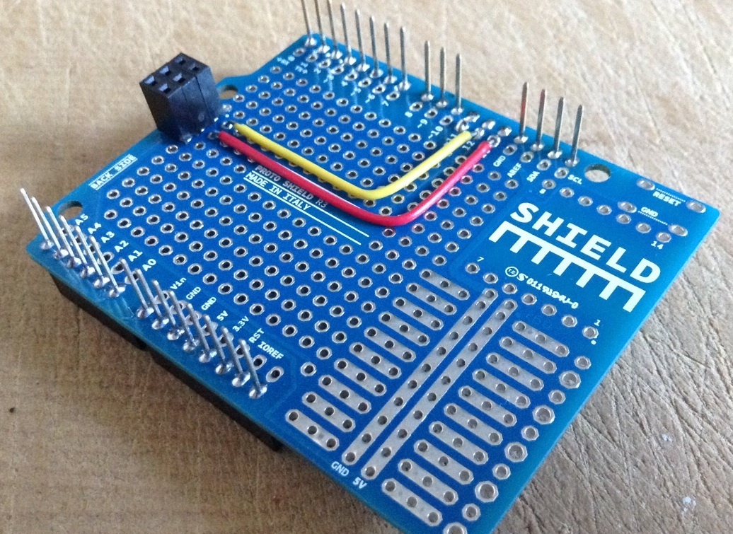
Pins 11, 12 and 13 are removed, but still connect to the stacked header on the opposite side of the board.
The board is very simple, all the usual Arduino Uno pins are passed through as expected, however pins 11, 12 and 13 are routed to the ICSP header to match the Arduino documentation.
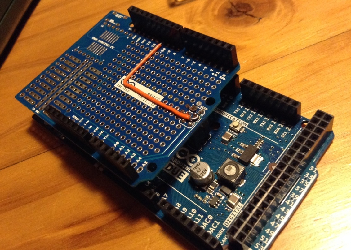
Here is a picture of the shield mounted on the Due. The trace for pin 11 is run on this side of the board to avoid crossing pin 13. I felt this was important as SPI can run upwards of 16 Mhz, however I’m not sure how much improvement this will make as these traces are still long and unshielded.
Here is a shot of result. The SD shield is mounted without floating pins or jumper wires and additional shields can be mounted on top of the SD card shield with the original locations of the SPI pins respected.
