Mea culpa
In my first post I said that I believed the simulator performance was 10x slower than a real PDP-11/40, sadly it looks like that estimate was well off by at least another factor of 10. Yup, 100x slower than the machine I tried to simulate. At least.
More accurate profiling
After my last post a commenter suggested that my counter based approach could be improved. It had a high overhead, and, as I discovered, was overstating the performance of the simulator.
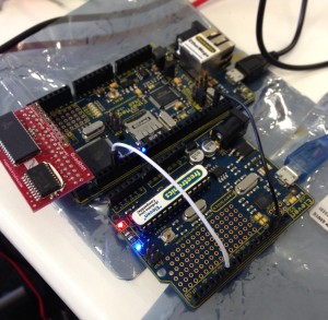
Adapting Joey’s approach a little I built a simple contentious frequency counter by adapting this Instructable.
Doing some calibration at the local hacker space with some other frequency counters and generators I believe the counter is accurate in the hundreds of kilohertz range, so certainly good enough for the job at hand.
The results
As I mentioned in a previous post there are two important timing points in the avr11 bootup cycle. The first is sitting at the
@
prompt, waiting for someone to type unix. At this stage avr11 running on the Atmega 2560 was processing 15,477 instruction/second. At this point the program is executing from a low area of memory and the MMU is not enabled.
Once unix is entered and the kernel has booted to the
#
prompt, the simulation rate drops to around 13,337 instructions/second. Executing a simple command like DATE, the simulation drops again to between 10,500 and 11,000 instructions/second.
Bringing a knife to a gun fight
As much as I love the minimalist idea of building a ’70’s era mini computer on an 8 bit microcontroller, it looks like this just isn’t going to be practical to build a usable simulator on the 16mhz Atmel 2560.
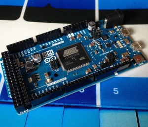
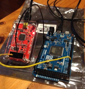
So, it was time to bring out the big guns. A quick visit to the Little Bird Electronics store and I had an Arduino Due on order.
The SAM3X chip at the heart of the Arduino Due is a full 32bit ARM processor which runs the Thumb2 instruction set. It also runs at a much higher clock rate, 84Mhz, vs the 16Mhz of the Atmega parts1.
The night the Arduino Due arrived I modified avr11 to run on it. The result, with just a recompilation of the code for the SAM3X processor; 88,000 instructions/second.
Depending on how you cut it, this is between 5 and 8 times faster
So just how fast was a PDP-11/40
I recently came across Appendix C, in the 1972 PDP-11/40 processor handbook which provides formulas for calculating instruction timings taking into account the time to fetch the operands and process the instructions.
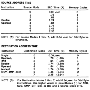
Source and destination operand times depending on the mode (register, indirect, register indirect, absolute, etc)
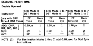
Sample instruction timings, these times are in addition to the time to fetch the source and destination operand.
So, now we can compute how long a PDP-11/40 took to execute an instruction, maybe this could be used to give some idea of how well avr11 was performing in simulation.
Taking the instruction
ADD R0, R1
Which adds the value in R0 to R1 and stores the result back in R1 should take 0.99us as R0 and R1 are registers (mode 0). For this simple instruction, assuming ideal conditions; no interrupts, no contention on the UNIBUS, etc, means the PDP-11/40 could have executed 1 million 16bit ADDs per second.
So, what can avr11 running on a 84Mhz Arduino Due do ?
I modified avr11 to execute ADD R0, R1 over and over again (effectively disabling the program counter increment) and timed the results.
Freq: 85344
Well, that isn’t great, 8.5% of the real simulation speed. However, that was for a best case instruction with no operand overhead. What if the instruction was more complex, for example ADD (R0), (R1)2, add the value at the address stored in R0 to the value in the address at R1. Using the tables above the timing on a real PDP-11/40 would have been 3.32 microseconds, 3.32x times slower, just over 300,000 instructions a second.
Altering avr11 to execute this new instruction sequence results in 63,492 instructions/second. Not exactly the result we were looking for, but putting the results into a table reveals something interesting.
| Instruction | PDP-11/40 | avr11 (Arduino Due) | Relative performance |
ADD R0, R1 |
1,000,000 hz | 85,344 hz | 8.5% |
ADD (R0), (R1) |
301,204 hz | 63,493 hz | 21% |
So, perhaps all is not lost. Maybe with a more realistic instruction stream the performance of avr11 is not in the single digits anymore. Being able to deliver 25%, 30% or even 40% of a real PDP-11/40 would be a significant milestone, and maybe one that is possible.
Next steps
Now that I have switched to the Arduino Due I’m going to have to revisit several solved issues.
The first is memory. The Due only has 96kb of SRAM, and while I can boot V6 UNIX in that tiny amount of memory, there is roughly 10.2 kilobytes of memory free for user programs once you get to the shell. For the short term I’ll have to revert to my SPI SRAM shield, modifying it to use the Arduino R3 spec’s IOREF pin rather than blindly dumping 5v across the input pins.
The second problem is the micro SD card. This was a question I had dodged originally by using the Freetronics EtherMega, but as the Ardunio Due has no onboard microSD card adapter I’m going to use something like the Sparkfun microSD shield3.
- I did briefly consider the Freetronics Goldilocks which is clocked at 24Mhz in a more 5v friendly format, but they aren’t easily available.
- In the 1970’s this instruction was written as
ADD @R0, @R1but I’ve chosen to use the more familiar GNU as form. - The Sparckfun sheild has to be used in ‘soft SPI’ mode as the board itself expects the Arduino Uno style SPI interface broken out on pins D9 – D12 which is not available on any of the boards in the Due/Mega extended form factor.
Note that if you’re toggling the pin with PINx = (1<<PINxn) as I suggested in my previous comment, the frequency you're measuring is half the toggle rate — first toggle changes pin from low to high, next toggle changes pin from hight to low.
So if you're toggling the pin after every instruction, an observed frequency of 15,477 Hz represents 30,954 instructions per second.
Hi Joey,
Thanks for you comment, here is the code that I am using
https://github.com/davecheney/avr11/blob/master/avr11.cpp#L74
So PIN18 goes high every time the cpu is processing an instruction.
Cheers
Dave
Acknowledged! (should have checked your new code before commenting :-)
Thanks Joey. To be clear, I couldn’t quite figure out how your version worked so I used a simpler, slower, version. Can you explain how the pin is toggled off again ?
Well, couple of things.
First, I avoided using Arduino’s digitalWrite() function because it has a substantial overhead. On the 2560 the cost of digitalWrite() is 68 cycles for a non-pwm-capable pin, and as much as 100 cycles for a pwm-capable pin. At 16 MHz, that’s 4.5 us or over 6 us on a pwm pin.
Each pin on the Arduino can be accessed much more efficiently by manipulating its I/O register directly. It does require a knowledge of which GPIO pins are mapped to which I/O register, which bit, and which Arduino pin. That information is available via the link in my very first comment.
Your chosen pin (pin 18) isn’t capable of PWM, so the cost of digitalWrite() is 4.5 us.
On the Arduino Mega 2560, the pin 18 is on PORTD, bit 3. We can turn the pin HIGH with:
PORTD |= (1<<3);
We can drive it LOW with:
PORTD &= ~(1<<3);
Each of these will compile into a single instruction taking only 2 cycles to execute, or 0.125 us.
The second thing is that modern AVR like the 2560 permit the toggling of a GPIO pin by writing a one to the PIN register, which is the register normall used to read the state of the pin. These are the registers accessed by digitalRead().
We can toggle the output state of pin 18 with:
PIND = (1<<3);
If the pin was LOW, it will be toggled to HIGH. If it was HIGH, it will be toggled LOW. It also compiles to a single instruction taking 2 cycles.
My suggestions was to do the following:
cpu::step();
PIND = (1<<3);
The overhead is 0.125 us per PDP11 instruction.
You could also do:
PORTD |= (1<<3);
cpu::step();
PORTD &= ~(1<<3);
The overhead is 0.25 us per PDP11 instruction.
To compare, with a measured frequency of 10,000 Hz, each instruction takes 100 us. However that includes the two calls to digitalWrite() at a cost of 9 us. Without the calls to digitalWrite() the simulation would be 10% faster.
Somewhat ironically, using digitalWrite() in this way probably has a worse impact than your initial technique of using millis() with a counter. Switching to one of the above forms will reduce the impact to a small fraction of a percent.
In either case, remember to configure the pin as an output with pinMode().