Woot! This project was featured on Hackaday.
mega6502, a big mess of wires
No Apple 1 under the tree on Christmas Day ? Never mind, with a 6502 and an Arduino Mega 2560 you can make your own.
The Apple 1 was essentially a 6502 computer with 4k of RAM and 256 bytes of ROM. The inclusion of a 6821 PIA and a Signetics video encoder meant that the Apple 1 shipped with its own 2400 baud dumb terminal built in. Just supply your own keyboard, composite monitor, and you were in business.
The good news is we can emulate the RAM, ROM, PIA, and all the glue logic with an Arduino.
The hardware
To validate the idea that an Ardunio could provide a stable clock for the 6502, I started by breadboarding the project.
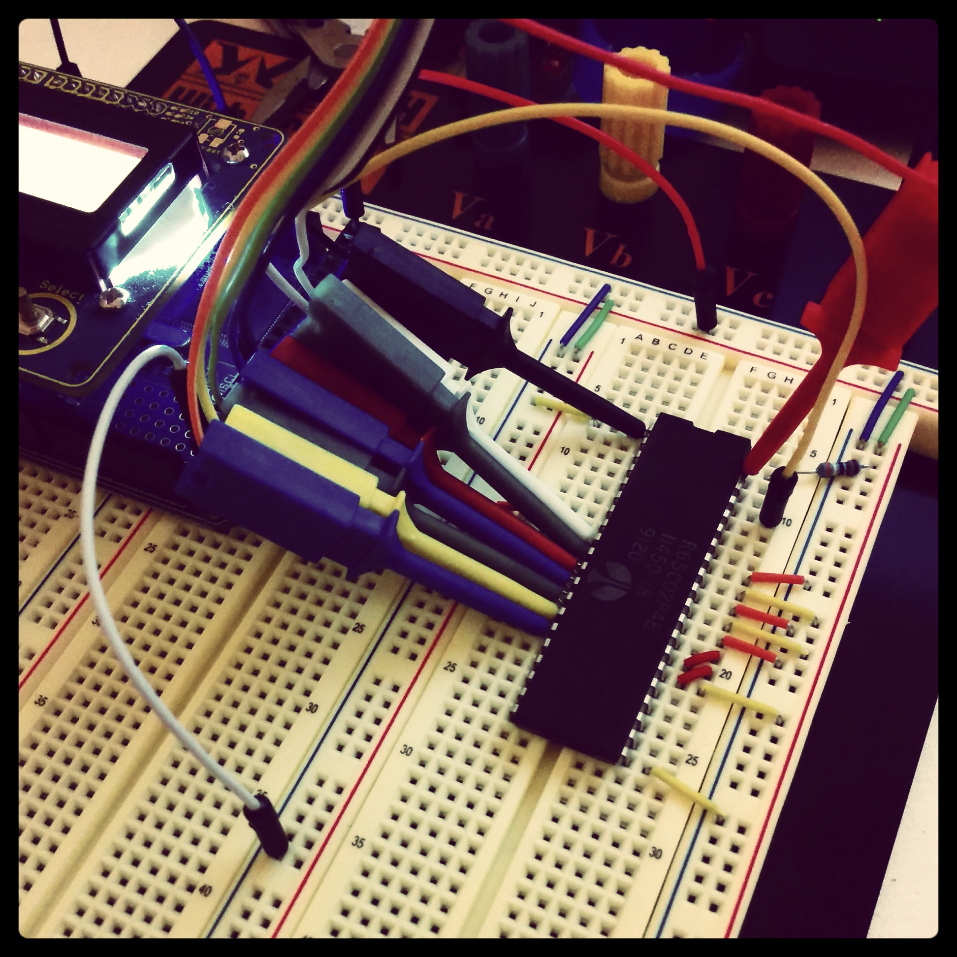
6502 strapped for $EA
The result was a success, with a tight assembly loop I was able to generate a 1Mhz clock with a roughly 50% duty cycle. So it was on to a prototype.
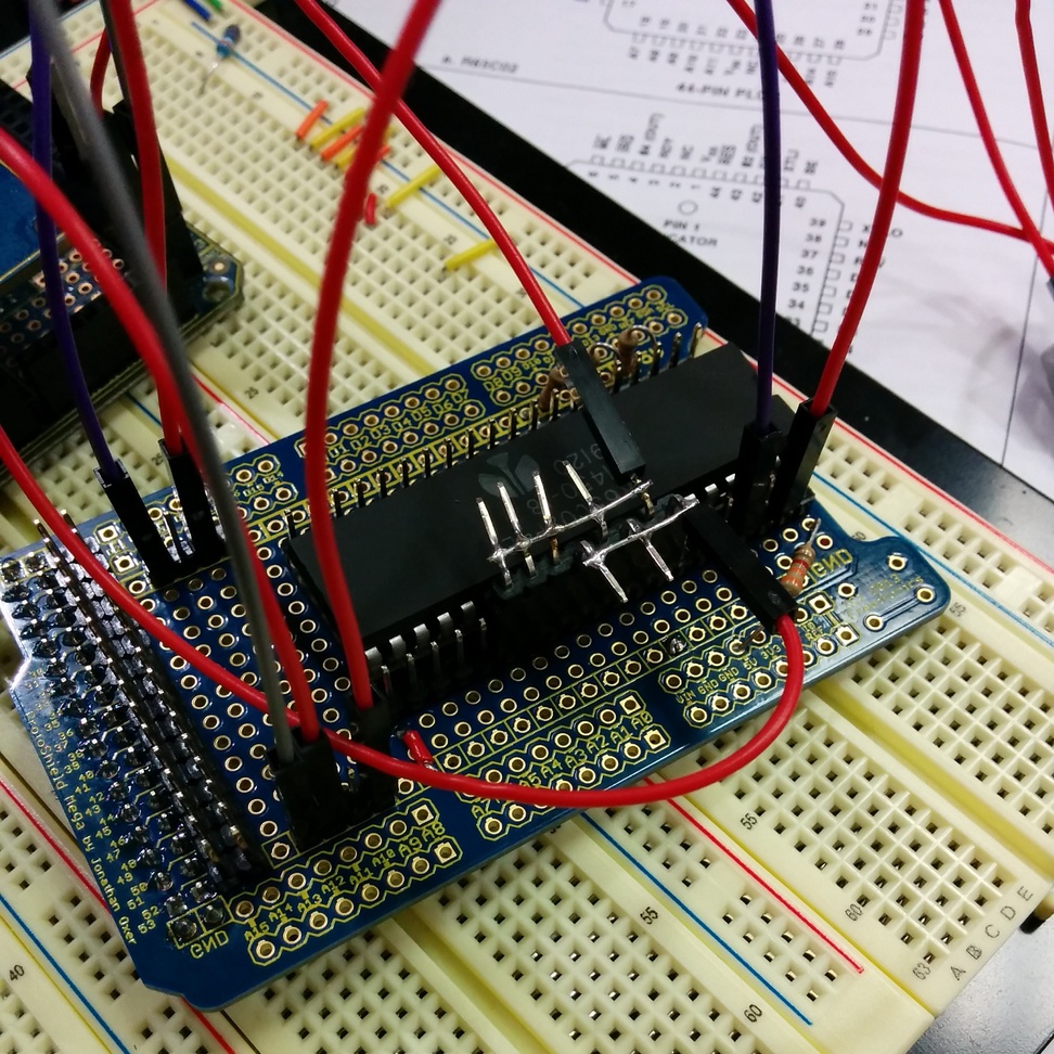
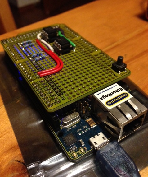
Prototype 6502 “sidecar”
The protoshield has 0.1 inch connectors for the 40 pins on the 6502 and the 40 something pins on the Ardunio Mega’s expansion header allowing me to jumper between the 6502 and the Arduino. The strange jumper block presents $EA on the data bus unconditionally, this is called free running mode.
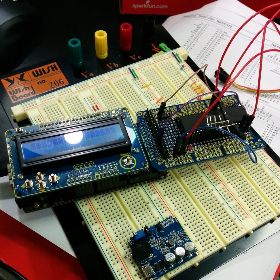
Mega6502 prototype
Because I wanted to use an LCD panel for debugging and the patch wires on the protoshield would not fit under the LCD shield I mounted the shield backwards and upside down, which retained the same pin outs (including 5v on the top). I called this prototype design the “sidecar”.
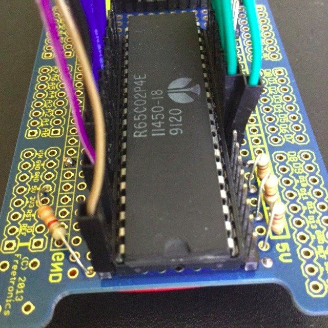
Sidecar wiring in detail
The schematic for wiring the sidecar to the Arduino is detailed in the README file.
The software
At the moment the software is a simple Arduino IDE sketch, you can find it on Github.
Clock
The Arduino provides the ϕ0 clock signal as part of the main loop() function. The 6502 interacts with the outside world on the falling edge of this clock (actually a few ns after ϕ0, the falling edge of ϕ2). It produces the address and read/write signals on the rising edge of ϕ0.
Different 6502 models have different requirements for the minimum and maximum length of each phase of ϕ0. The original NMOS 6502 required a clock of at least 100khz to avoid loosing internal CPU state, which made single stepping more complicated. With the Rockwell 65c02 I am using the ϕ0 low phase must not exceed 5μs, but the clock signal can remain high indefinitely (the fully static WDC 6502 removes any restriction on a minimum clock).
We can use this property to generate a stable ϕ0 low around 500 ns (the minimum instruction time on a 16Mhz Atmega is 62.5ns), then raise ϕ0 and do our processing, even take an interrupt. Because I have the 4Mhz 65c02 version, we can even make the ϕ0 low period shorter, to allow our high pulse to take longer in an effort to reach the 1Mhz clock target.
Laughton Electronics has published a fantastic page if you want to learn more about the 6502 timings.
Ram
The Apple 1 divided the 6502’s address space into 16 4k banks which could be assigned to RAM, ROM, or I/O.
The 2560 includes 8kb of SRAM, so we dedicate 4k to be the bottom bank of ram starting at $0000, which is more than enough for a usable replica. For Apple 1’s with 8kb of ram, the second bank of ram was usually strapped to $E000 and used for BASIC. The nice property of this is we can replace the $E000 bank with a ROM image mapped to that location (BASIC did not expect to be able to write to memory at $E000) and achieve the same effect without providing another 4k of RAM.
ROM
The original 256 byte Woz monitor rom is provided at $FF00. For simplicities sake the ROM is mirrored at every page in the $F000 address space.
I have tested a few of the popular ROM images like A1Assembler and Applesoft-lite but only include the Woz monitor rom in the source distribution. Enterprising readers should have little difficulty modifying the source code to include additional ROM images.
Input and output
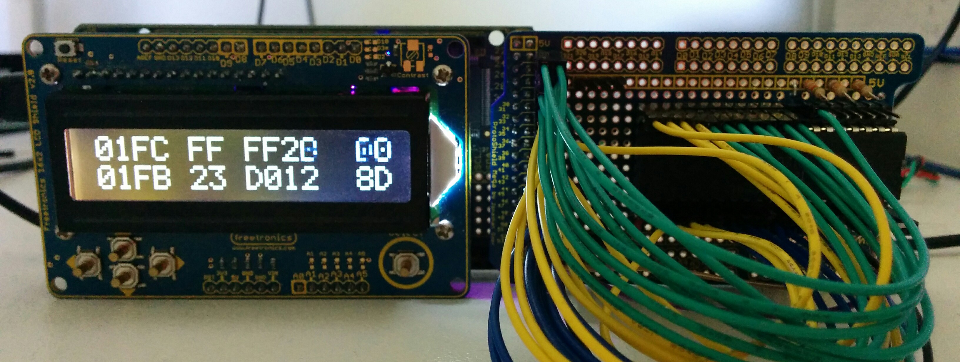
The Apple 1 interfaces to the keyboard and screen via four registers from the 6821 PIA chip mapped into the address space at $D000.
When a key is pressed on the keyboard, the high bit of $D011 is latched high, this can be detected by the 6502 ROM monitor which then reads $D010 to fetch the keycode, which is conveniently encoded as 7bit ASCII.
Output is similar, the 6502 polls $D013 until the PIA reports that the video encoder is not busy then the character to write to the screen is placed in $D012.
It is straight forward to map these reads and writes to these addresses to the Arduino serial port. Again for simplicity, the PIA is mirrored to every page in $D000.
The speed
Like my previous projects, performance is always a problem. Assuming a 50% duty cycle for the ϕ0 clock, a 16Mhz Atmel has 8 cycles to decode the address and read/write the data. This is basically impossible. However, as I am using a Rockwell 65c02 cpu, which is CMOS, and a higher speed grade than the original NMOS based 6502, we can cheat and shorten the ϕ2 low, trading that time for a longer ϕ2 high pulse.
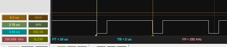
Just shy of 300khz
Using my trusty Bitscope Micro, I can probe the ϕ2 clock. You can see the asymetry between the high and low phases. The high phase is currently 2.8μs, or around 45 cycles for the Arduino. This equates to a clock speed of just under 300khz, which is very usable.
Demo time
Here is a short video showing the mega6502 running a short BASIC program in debug mode.
Here is a screen capture showing David Schmenk’s 30th birthday demo for the Apple 1.
Next steps
- More tweaking of the decode logic to try to reduce the ϕ2 high period.
- Implement a faux cassette interface possibly using the SD card for cassette storage
- A new design using an Atmega1284P — a minimalistic two chip SBC 6502 solution, assuming I can find a bootloader that works.
Resources
If you liked this project, check out some other fantastic 6502 projects.
- Project:65
- Quinn Dunki’s fantastic Veronica. We are not worthy!
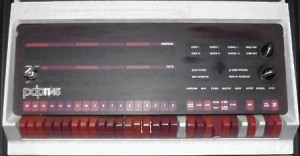
- PDA6502, Paul has designed his own 6502 solution from scratch.
